

STL檔案準備
專業的3D列印STL設計規格,涵蓋解析度最佳化(弦長/角度公差)和7種常見網格錯誤的解決方案,確保可列印性。
STL-file-preparation
1. STL File
STL file is the standard file format for 3D Printing, it is the acronym of Standard Triangle Language/ Standard Tessellation Languages/ StereoLithography.
STL files are the translations of 3D models in which all information is stored. It consists of a series of linked triangles that describe the surface geometry of a 3D model without representing color, texture, or other common model attributes. The more complex the 3D model, the more triangles are used, and the higher the resolution.
As the most commonly used file format for 3D Printing, all STL file can be created by CAD (computer-aided design) model program. By identifying STL files with .stl file extension, STL files are exported.
Before 3D Printing, the STL file needs a tool called 3D slicer to chop up the file into hundreds and sometimes thousands of flat horizontal layers. Slicer is a 3D Printing software that converts digital 3D models into printing instructions for your 3D printer to create an object. In conjunction with 3D slicer, it allows a computer to communicate with 3D Printer to ensure that the file is printable.
Export STL File in Correct Resolution
As STL file uses a series of linked triangles to recreate the surface geometry of a 3D model, while the higher the resolution, more triangles will be used, and STL file size will be larger. Choosing the right exporting parameters to optimize the surface of 3D model, which the main parameters are chordal tolerance and angular tolerance.
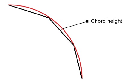
- Chordal tolerance controls the global dimensional accuracy of STL files. It is recommended that the chordal tolerance better set as 1/20 of the 3D Printing layer thickness, but never less than 0.001mm. The smaller chordal tolerance value will result in a higher resolution STL file with more triangles and larger file size.
i.e.:
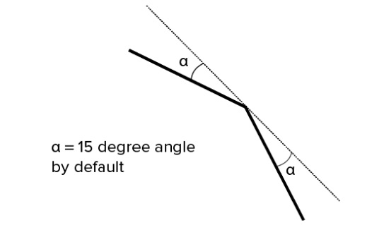
- Angular tolerance controls the maximum angle allowed between the normal vectors of any two neighbouring triangles in the mesh. Angular tolerance measures in degrees, a lower value resulting in a higher resolution model. Specifying the angular tolerance as a dimensionless angle control parameters that varies in value from 0 to 1 to make the STL in high resolution.
i.e.:
| Materials | 5*5mm | 10*10mm | 50*50mm | 100*100mm | 200*200mm |
|---|---|---|---|---|---|
| Somos® GP Plus 14122 C-UV 9400E Somos Tough Resin Somos® Taurus Somos® LEDO 6060 | 0.6mm | 0.8mm | 1mm | 1.2mm | 1.5mm |
| Somos® WaterShed XC 11122 | 0.4mm | 0.8mm | 1mm | 1mm | 1.2mm |
Please remember that avoid exporting unnecessarily large STL files. Upload STL file on Kings3D instant quoting engine and we will help you optimize and fix the file.
Tips:
- Set chordal tolerance as 1/20 of the 3D Printing layer thickness, but never make it less than 0.001mm.
- Specify the angular tolerance in a value from 0 to 1.
3. Avoid exporting unnecessarily large STL files.
STL File Common Errors
1. Noise Shells
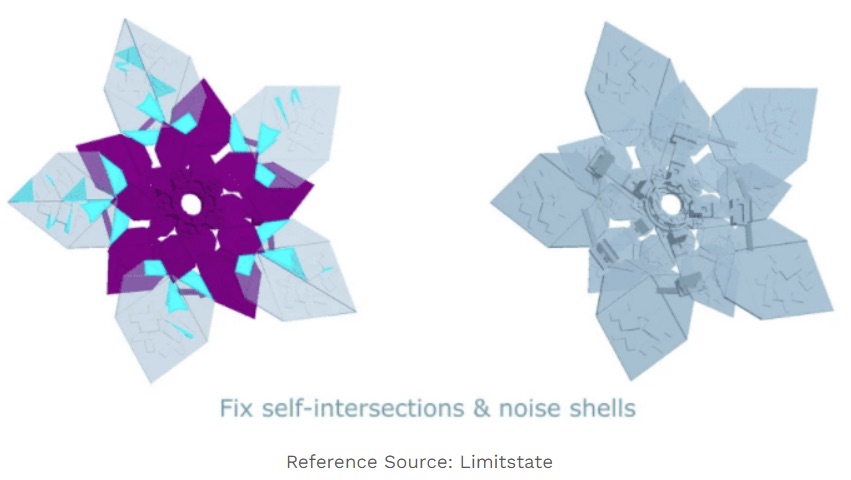
The external layers of a 3D model are made up by shells. Noise shells are shells that are too small to build the outer layers of the model, which are redundant and useless. If there are too many small shells presenting in the design, it may take longer printing time.
i.e.:
Solution:
Noise shells can be removed by flipping the inverted triangles to achieve a single solid before exporting. And repair software can easily detect the noise shells and remove them.
2. Intersecting and Overlapping Triangles
STL file composes of a mesh of triangles, and when two surfaces overlap and cross on another, it is called intersecting or overlapping triangles. Intersecting or overlapping triangles will usually lead to slicing failures or even printing failures. For example, if you input the STL file with intersecting or overlapping triangles into an SLS printer, the laser will pass that surface too many times, which may change the property of the material, and it will inevitably increase printing time and cost as the model will require more materials.
i.e.:

Solution:
Fortunately, it typically doesn’t take too much effort to repair such an error. These triangles can be unified or removed by the repair software.
3. Boundary Edges
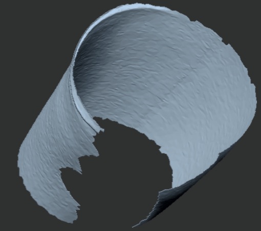
Boundary edges occur when if some edges of the STL file are not connected to only one face, which means the model has holes and an open surface that is not printable.
i.e.:
Solution:
Fine the holes and close them in the desired shapes. But how to close the hole will affect the original shape of the model. Choose FLAT or CURVATURE accordingly.
- Flat (FLAT) – The software will try to fill the hole with as flat a surface as possible. Recommended for engineering models with straight surfaces.
- CURVATURE – The software will try to analyse the geometric structure around the hole and track this geometry as the hole is completed. Recommended for amorphous models with curved terrain.
4. Non-manifold Edges
Non-manifold edges occur when more than two faces are attached to the same edge. There are two cases of non-manifold edges:
- An extra surface inside the model, which splits the model into two.
i.e.:
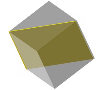
Solution: Delete the excess surface.
- Two elements share one edge, which makes two model into one.
i.e.:
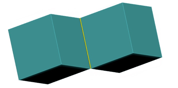
Solution:
- If two elements are intended to connect with each other, the solution is increasing the thickness of the connection between the two elements to the recommended wall thickness in the selected printing technology.
- If two elements are two separated elements, the solution is increasing the distance between two elements. It is recommended to save two elements in one STL file when placed as needed.
5. Colliding Surfaces
When STL file consists of several parts of the model, and there should be a space between these parts, but somehow, they collide with each other. It creates an internal space inside the model and the slicing software can not recognize.
Solution:
When modelling, make sure to maintain the desired spacing between the parts. Merge the separate model parts when they are at the desired spacing for a single STL file.
6. Colliding Polygons
Colliding polygons are the product of a faulty division of the polygon mesh.
Solution:
Spot delete the colliding polygons. The eraser usually creates a hole and can be closed using the methods described.
7. Holes or Gaps in A Mesh
Holes or gaps in a mesh occur when the adjacent triangles fail to share two common vertices. If this error is overlooked, the printer will not be able to correctly print the design.
i.e.:
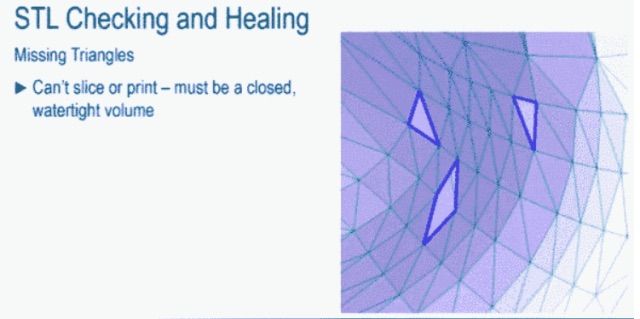
Solution:
Repair software can easily detect the missing triangles.
8. Over-refined Mesh
When the total number of triangles of the STL mesh is larger than required, it is called the over-refined mesh. It will not lead to any errors when printing, but it is difficult the deal with the unnecessarily large STL file. Besides, those tiny details cannot by printed.
Solution:
Use the default setting of the CAD software when export the STL file or follow the STL file correct resolution guidelines.