

Руководство по SLM-печати металлами
Полные правила проектирования для SLM 3D-печати металлами: толщина поддерживаемых/неподдерживаемых стен, минимальные размеры отверстий, рельефные/гравированные детали, допуски (±0,2 мм или 0,2%), рекомендации по конструкциям поддержки, стратегии ориентации, дизайны самоподдерживающих каналов для AlSi10Mg и нержавеющей стали 316L.
SLM- Metal- Printing- Guide
Minimum Unsupported Overhang Angle
Recommendation: >20° from level
Minimum Clearance
Threads and Screws Design Requirements
Tolerance
200μm or 0.2%
MJF Printing Rules
Printing Theory
MJF, Multi Jet Fusion, is a process that deposit both fusing and detailing agents onto the powder bed by an inkjet head, then fusing the materials by infrared heating unit into a solid layer until the object is formed.
Design Rules
Supported Wall
Unsupported Wall
Minimum Hole Diameter
Minimum Escape Hole Diameter
Recommendation: > 2.0 mm Diameter
Minimum Vertical Post Thickness
Minimum Embossed Detail
Minimum Engraved Detail
Minimum Unsupported Overhang Angle
Recommendation: >20° from level
Minimum Clearance
Threads and Screws Design Requirements
Tolerance
200μm or 0.2%
SLM Printing Rules
Printing Theory
SLM, Selective Laser Melting, is a technology that uses metal powder to be completely melted under the heat of laser light with high energy, then the parts are cooled and solidified layer by layer.
Design Rules
1. Supported & Unsupported Wall
| Materials | 5*5mm | 10*10mm | 50*50mm | 100*100mm | 200*200mm |
|---|---|---|---|---|---|
| AlSi10Mg | 0.4mm | 0.4mm | 0.5mm | 0.8mm | 1mm |
| 316L Stainless Steel | 0.3mm | 0.5mm | 1.2mm | 2mm | / |
2. Minimum Hole Diameter
| Materials | Diameter (vertical) |
|---|---|
| AlSi10Mg | 0.5mm |
| 316L Stainless Steel | 0.5mm |
3. Minimum Escape Hole Diameter
Recommendation: > 2.0 mm Diameter
4. Minimum Vertical Post Thickness
| Materials | Supported Post | Unsupported Post |
|---|---|---|
| AlSi10Mg | 0.5mm | 0.5mm |
| 316L Stainless Steel | 0.5mm | 0.5mm |
5. Minimum Embossed Detail
| Materials | Width | Height | Distance |
|---|---|---|---|
| AlSi10Mg | 0.2-0.3mm | 0.2mm | 0.3mm |
| 316L Stainless Steel | 0.2-0.3mm | 0.2mm | 0.3mm |
6. Minimum Engraved Detail
| Materials | Width | Height |
|---|---|---|
| AlSi10Mg | 0.8mm | 0.5mm |
| 316L Stainless Steel | 0.8mm | 0.5mm |
7. Tolerance
±0.2mm or 0.2%
Rules Of Thumb
Surfaces in 0-45 degrees angle in relation to the build platform require support structures.
The recommended max size for round holes without support structures is 3mm.
Make the channels and holes self-supporting if possible.
Make the part as light as possible.
Round the corners if possible.
Size
At OLA3D we employ two SLM metal printers, BLT and HBD. The size of the build chamber dictates the max size for printed parts:
BLT 250mm x 250mm x 300mm
HBD 320mm x 320mm x 400mm
About Support Structures
Support structures are used in metal printing to support the part while printing and also for conducting the heat away from the body. In principle every part should be designed so that it’s easy to support since all the supports will be modeled in place according to the printer. The supports are printed with the part connecting the part to the printer’s build platform. The supports are removed after printing in post processing so their number should be minimised wherever possible. Also the surface quality is affected by the supports but this can be dealt with different post processing techniques.
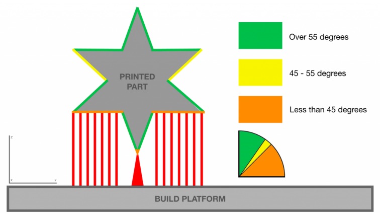
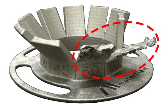
All the surfaces that are in 0-45 degrees angle in relation to the build platform require supports. For quality control surfaces with 45-55 degrees should also have supports since 45 degrees is still a critical angle. Image 1 shows a supported part attached to the build platform. The colors indicate the angles in relation to the build platform.
Limitations
Orientation
When designing a part always consider orientation. Orientation plays a key role in printing and in surface quality. In general the upskin surface has better quality compared to the downskin. Usually the downskins require supports which affects the surface quality even more.
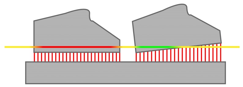
It is advised to tilt the part in relation to the X and/or Y axis to minimise the amount of layer area to fuse when printing. This also minimises thermal voltage and warping effect. In Image 3 the horizontal line depicts a single build layer. The image shows how the object on the lefthand side is affected more by thermal voltage (the red part of the line) because the laser fuses more material simultaneously. The tilted object on the righthand side is less affected.
Holes And Channels
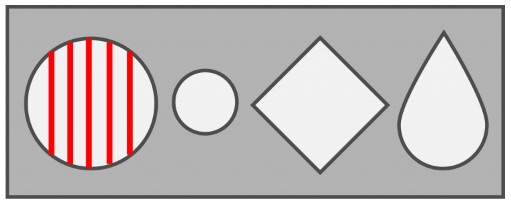
Internal channels must be taken into consideration when orienting a part. In some cases it is difficult or even impossible to remove internal supports so the channels should be self-supporting and/or in 45-90 degrees angle in relation to the build platform. Channels shaped as drop, diamond, ellipse and triangle are self-supporting.
Image 4 shows how a round hole with a diameter over 3mm needs supports. Shorter holes can be drilled to remove the supports but with longer internal channels the removal becomes difficult. The drop shaped profile is self-supporting and doesn’t need supports. With different shapes the walls should be at least in 45 degree angle in relation to build platform. The higher the angle, the better the surface quality and less margin for errors during printing.
Holes and channels with threads should be printed vertically without supports. Usually the threads require post processing with a thread tap after printing.
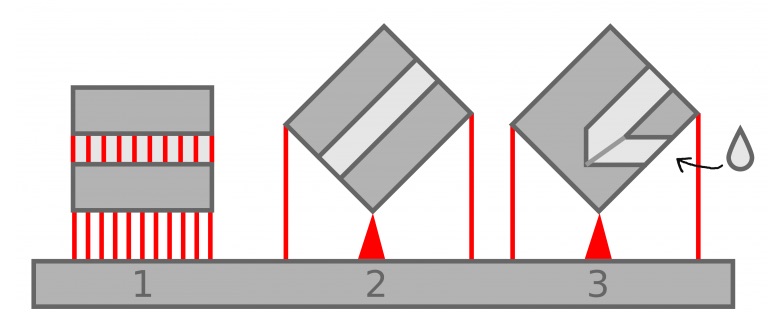
Image below shows three options to support a channel over 3mm in diameter. Option 1 requires supports which affects the surface quality and increases the workload in post processing. The down skin has too many unnecessary supports and the horizontal orientation causes too much thermal voltage on the large surface which can cause warping.
Option 2 is an optimal way to orient and print the object in question. Since the surfaces have an angle over 45 degrees in relation to the build platform the down skin and internal channel won’t require supports. The supports are only needed on the bottom edge and on the sides to keep the object in balance.
Option 3 depicts a similar object with a channel in a different angle. In such cases it is advisable to design the channels to be self-supporting i.e. a drop shape or similar instead of a round one.
Optimise Your Model For 3D Printing
Make The Part Lighter
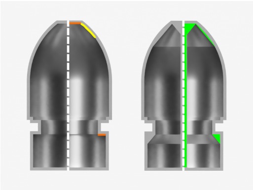
To cut production costs your parts should be as light as possible. This can be achieved by designing the parts so that the raw material is only used/added where it’s actually needed. Printing hollow parts has some limitations since the structure usually needs inside supports. In these cases self-supporting surfaces work very well. Image below shows two versions of a hollow object. The first one has surfaces that need supports. The second is fully self-supporting. It is also advisable to have at least one hole over 2mm in diameter to ease the removal of excess and unfused powder in post processing.
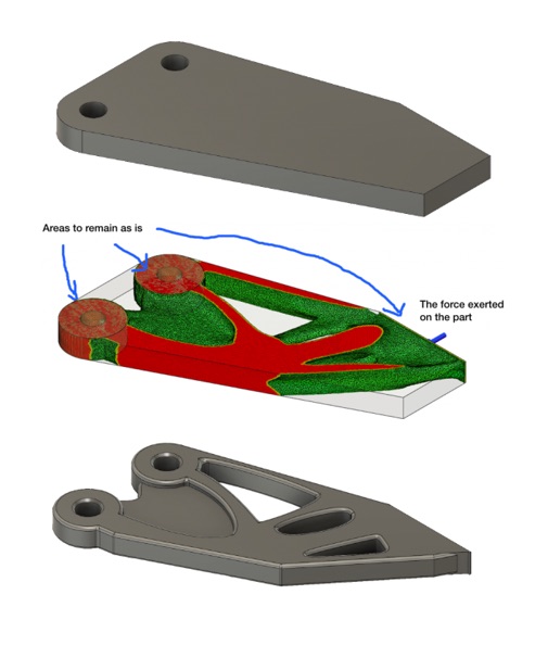
With some modeling softwares you have the option to perform a load simulation and a stress simulation. This so called topological optimisation helps to identify the surfaces and areas that won’t add value to the parts mechanical performance and therefor only add unnecessary mass. Topological optimisation depicted in images below.
Rounding The Corners And Edges
Rounding eases the thermal voltage that usually accumulates on the sharp corners and edges during printing. If possible it is advisable to round off sharp corners and edges since it also increases the parts mechanical durability in general.